• 500+ integrators
  • 5,000+ projects completed
  • 12-year warranty on pixels
  • Designed and integrated in Canada
  • Canada · United States · Europe
  • cULus · CSA · CE · RoHS
  • Cloud or local app
  • 20 years of experience in home automation

Training Center · COB Linear Systems · Strip

The COB.
Install.
Master.

Everything you need to install a COB strip, from the housing to the last end cap: manual, videos, wiring cheat sheet, cutting and soldering instructions, and controller setup.

First time installing?

Start here.

The three key elements of a successful COB line. See the checklist below for details.

01

Draw the line before cutting

A 5-meter strip = one combined output, fed from one end. A 10-meter strip = two outputs, fed from both ends. Never more than 20 feet per output. The enclosure must be 30 feet or less from the strip. Draw up a plan on paper: segments, joints, outputs, and zones.

02

Lay flat; never fold

The key to aluminum extrusion is the heat sink. Don’t bend it, don’t force it into a curve, and don’t step on it. To create a corner, use the IllumiDEL 90° plastic corner piece or cut it and rejoin the ends.

03

Seal each cup; test before closing

Each cut end is fitted with a COB cap and silicone; cure for 24 hours. Before installing the caps: turn on the line, verify that everything is functioning properly, and ensure that the end of each segment receives at least 22.5 V at 100% white.

Training videos

Review. Complete. Review again if necessary.

A complete installation filmed from start to finish, followed by short videos demonstrating the COB, Strip, and Neon systems. The nine videos marked “Coming Soon” are currently in production and will be added here as they become available.

Complete installation: 1capsule

COB · Strip ·Neon 4 / 13 capsules in a row

Quick Reference Guide · COB & Strip V2

From the case to the tape.
What you need to know by heart.

Wiring rules, cutting, soldering, and configuration—all on one page. The videos above demonstrate each step; this is the version you can review in five seconds on the job site. Excerpted from the COB & Strip V2 Manual, Rev. 2.3.

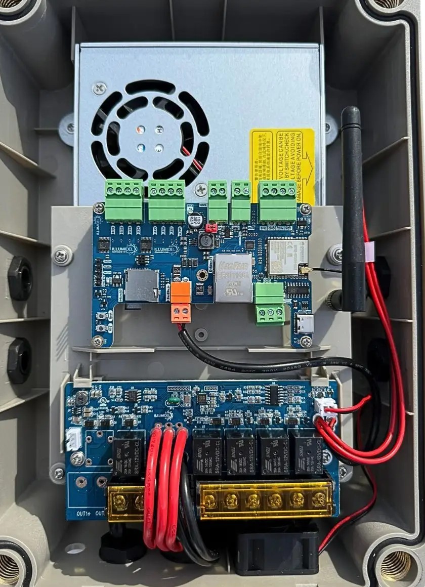
01Theenclosure: 8 data zones at the top, 4 combined outputs at the bottom

Interior of the IllumiDEL ILMC-24V-450W controller: power supply at the top, control board with 8 data terminals, output board with 4 combined outputs at the bottom 1 2 3 4 5 6
1
24 V Power Supply

ILMC-24V-450W: 4 fused outputs. ILMC-24V-600W: 5 outputs. 100–240 V AC input. Class 2 per output.

2
8 data zones — green terminal blocks, at the top of the board

D1 through D8, independent of the power outputs. The data line runs from here to the beginning of the line, and only there. A zone may span multiple merged outputs.

3
Control Chart

Wi-Fi, scenes, schedules. The reset button and the microSD card are here.

4
Wi-Fi Antenna

2.4 GHz. Do not trap it under the cover.

5
4 merged 24-V outputs — gold-plated terminal block, at the bottom

5 A fuse, limited to 100 W by electronic sensing (4.17 A). It is designed for 100 W, not 5 A: 20 ft of tape at 16 W/m, 18 ft at 17 W/m. The red (+) and black (−) wires run from here to the beginning of the tape or to a joint.

6
OUT+ / OUT− Markers

Screen-printed on the board. Each output powers a single section; never connect two outputs together, nor connect two enclosures via the 24 V+ line.

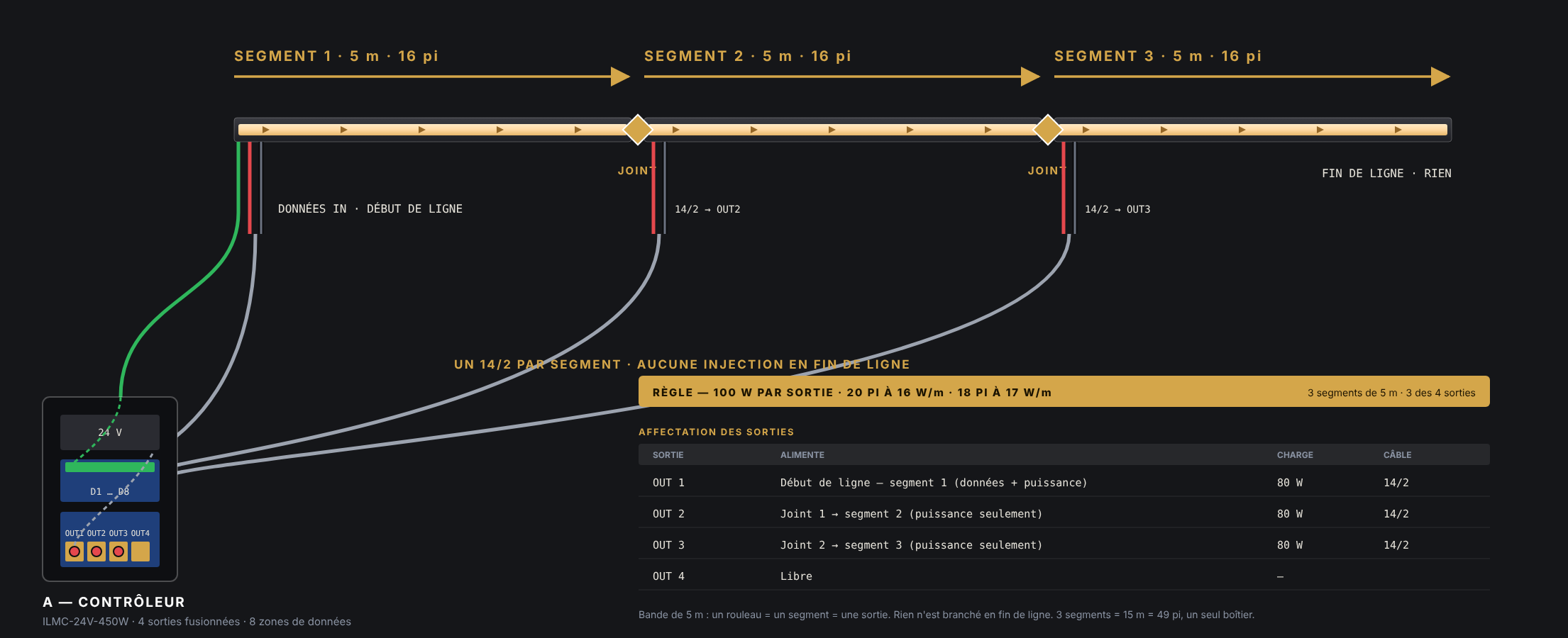
Figure 1: Three 5-meter COB strips in a line, one 14/2 wire per segment leading to a combined output; data enters only at the beginning, nothing at the end of the line
Fig. 1 — 5-meter strip: one segment, one output, a single fed end. Red: +24 V Gray/black: −24 V Green: data, from the enclosure to the start of the line, in the direction of the arrows 3 segments = 3 outputs · no signal injection at the end of the line
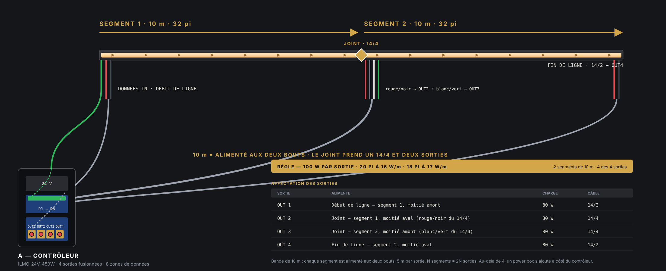
Figure 2: Two 10-meter COB strips, fed at both ends; at the junction, a 14/4 cable connected to two combined outputs; at the end of the line, a 14/2 cable connected to a fourth output
Fig. 2 — 10-meter strip: fed at both ends, 5 meters per outlet. Start of line: OUT 1 (data + power) Connector: a 14/4 → OUT 2 and OUT 3 End of line: a 14/2 → OUT 4 The data remains in zone D1 from one end to the other
More than 4 sections? Add a power box next to the controller: same enclosure, 5 additional fused outputs, no data. Each section is powered by a single enclosure. Connect the 24 V − terminals of both enclosures using 14 AWG wire (standard for data); never connect the 24 V + terminals.

02Thepath: housing → cable → tape, and the wire code

THE CASE ILMC-24V-450W · 4 outputs / 600W · 5 outputs 8 DATA ZONES · top D1 D2 D3 D4 D5 D6 D7 D8 one zone = one row of data 4 MERGED 24-V OUTPUTS · Low OUT 1 OUT 2 OUT 3 OUT 4 5 A · 100 W · 20 ft / output Data and power: two separate accounts enclosure within ≤ 30 ft of the strip DATA D1 → green wire MERGED OUTPUT 100 W · max 20 ft +24 Vrouge · 14/2, depuis OUT DONNÉESvert · depuis D1–D8, début de ligne seulement GND · 24 V −noir · 14/2 home run ≤ 30 ft (ideally ≤ 15 ft) · strip 10–12 mm · one WAGO per conductor COB STRIP · in extrusion +24V · DO · GND 3 settings at the start: DO on the case side data direction → cuts at 4 in. (101.6 mm) · scissors For each mark: DO on one side, DI on the other · never anywhere else all ends cut off: COB tip + silicone NEVER BEND · NEVER STEP ON IT · NEVER TURN IT ON WHILE IT'S ROLLING
Red = +24 V Case green = Data Black = 24 V − arrows = data direction, away from the housing
14/2 — red +, black −Start of line, end of line, 5-meter strip joints. Power only: one cable, one outlet, one section.
Data — a single point of entryFrom terminal block D1–D8 to the DO of the very first segment. They pass through every DO → DI connection. They are never fed into the line; feeding power into the line makes no sense.
GND — groundWith a power box, connect the 24 V − from both enclosures (14 AWG). The data lines require a common reference.
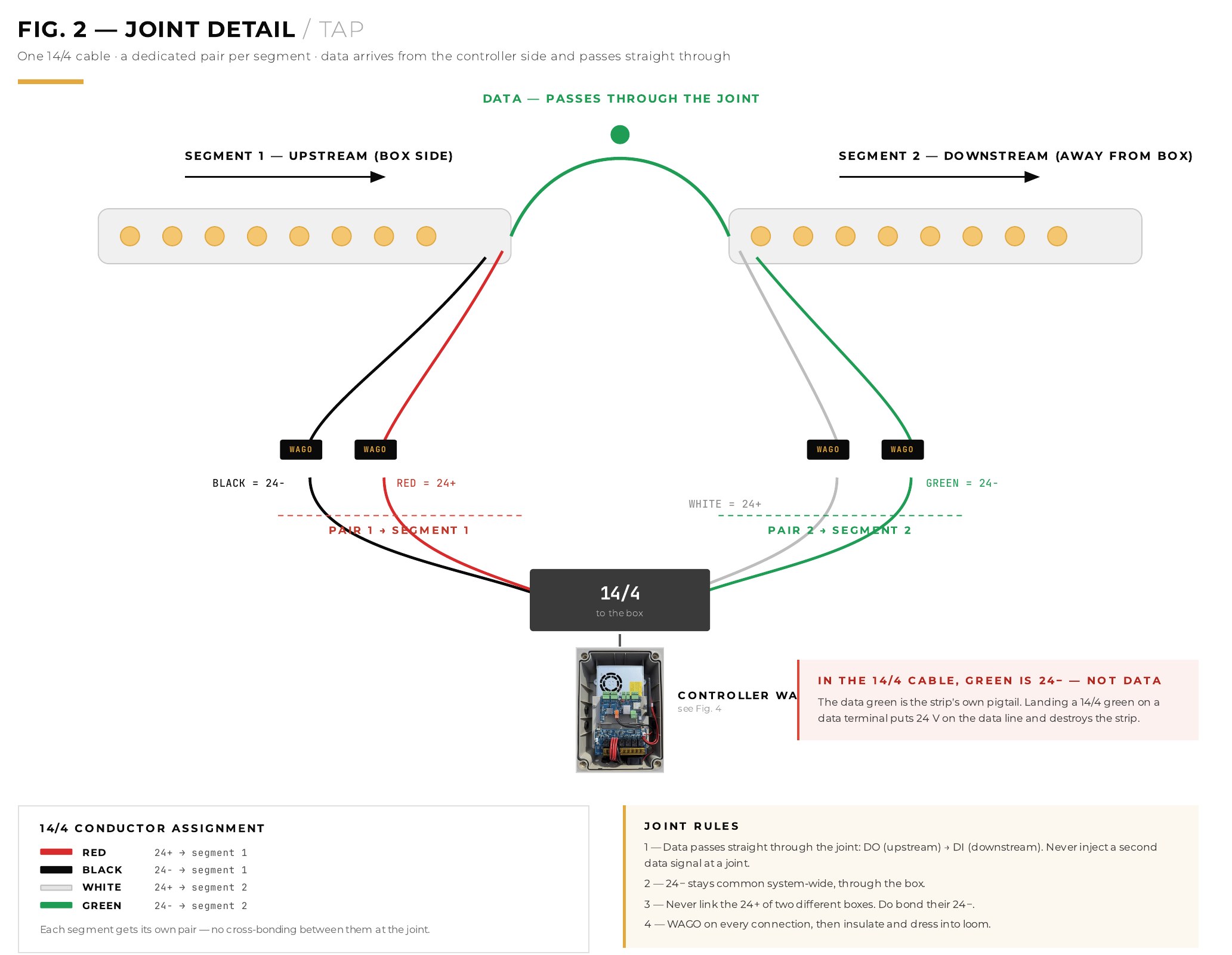
14/4 cable — for 10-meter strip joints and central power supplies

A 14/4 = two pairs = two outputs combined into a single cable. Each pair feeds one half of the joint.

PAIR 1 → upstream segment (housingside)
Red = +24 V
Black = 24 V −
→ a combined output
PAIR 2 → downstream segment (moving away from the housing)
White = +24 V
Green = 24 V −
→ another merged release
Two green wires, two meanings. In the 14/4, the green wire is a 24 V −. On the ribbon cable pigtail, the green wire carries data. Never connect the green wire from the 14/4 to DO/DI: there is no data in a 14/4. Label the pairs on the housing before running the cable.

03KeyFigures to Keep in Mind

20 feet · 6.1 metersMaximum per merged output

At 16 W/m (97.5 W). At 17 W/m: 18 ft (5.5 m). The limit is the 100 W detection threshold, not the 5 A fuse. A section powered at both ends: 40 ft / 36 ft.

5 m / 10 mTwo formats, two wiring configurations

5 m (16 ft): 14/2 at the start, nothing at the end; N segments = N outputs. 10 m (32 ft): fed at both ends, 14/4 at the joints; N segments = 2N outputs.

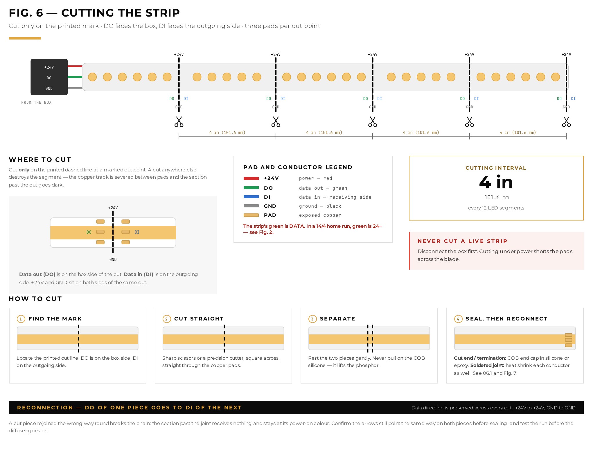
4 in.Cut marks

Every 101.6 mm, there are 12 LED segments between two marks. Cut straight across the printed mark with scissors—never between two marks. Each cut reveals three sections on either side.

5/8in.Strip the wire before connecting it to a WAGO connector

A WAGO connector with separate conductors and the lever firmly folded down. Too short: poor contact. Too long: exposed copper. Then apply heat-shrink tubing or electrical tape.

30feetMaximum home run

From the junction box to the tape, 14 AWG: 1.74 V drop at 30 ft. Ideal for 15 ft or less. The tape itself should be 20 ft or less from the junction box.

22,5VMinimum at the end of the segment

Measured at the farthest end of each segment, 100% white, before closing. Below this: home run too long, joint not tight enough, or outlet overloaded.

Never bend it; never force it to bend

The V2 strip is made of 3 oz double-layer copper: it breaks when bent. The only allowed bend is the 90° IllumiDEL plastic corner on the 2200B XL rail. Everywhere else: cut, turn, and reconnect using a connector.

The entire length is made of aluminum; it has never been lit on the roller

Extrusion acts as a heat sink: at 16–17 W/m, a strip left outside the profile or coiled up will overheat within a few minutes. Clips spaced 300–500 mm apart (250 mm on the ceiling), surface cleaned with 99% isopropyl alcohol, installation at temperatures above 10 °C, 100 mm operating loop, retaining clips on the outside or at temperatures above 35 °C.

04 Cutting, Sealing, and Welding

Cut

Cut the strip. Use scissors, straight across the mark. DO looks at the casing, DI looks at what comes next. Check the direction indicated by the printed arrow before cutting the second piece.

Connect: DO → DI, always

At the splice, the data exits the DO of the upstream segment and enters the DI of the downstream segment. Power is fed in at the same splice: a 14/2 (5 m strip) or a 14/4 (10 m strip). One WAGO connector per connection.

Weld along the visible lines

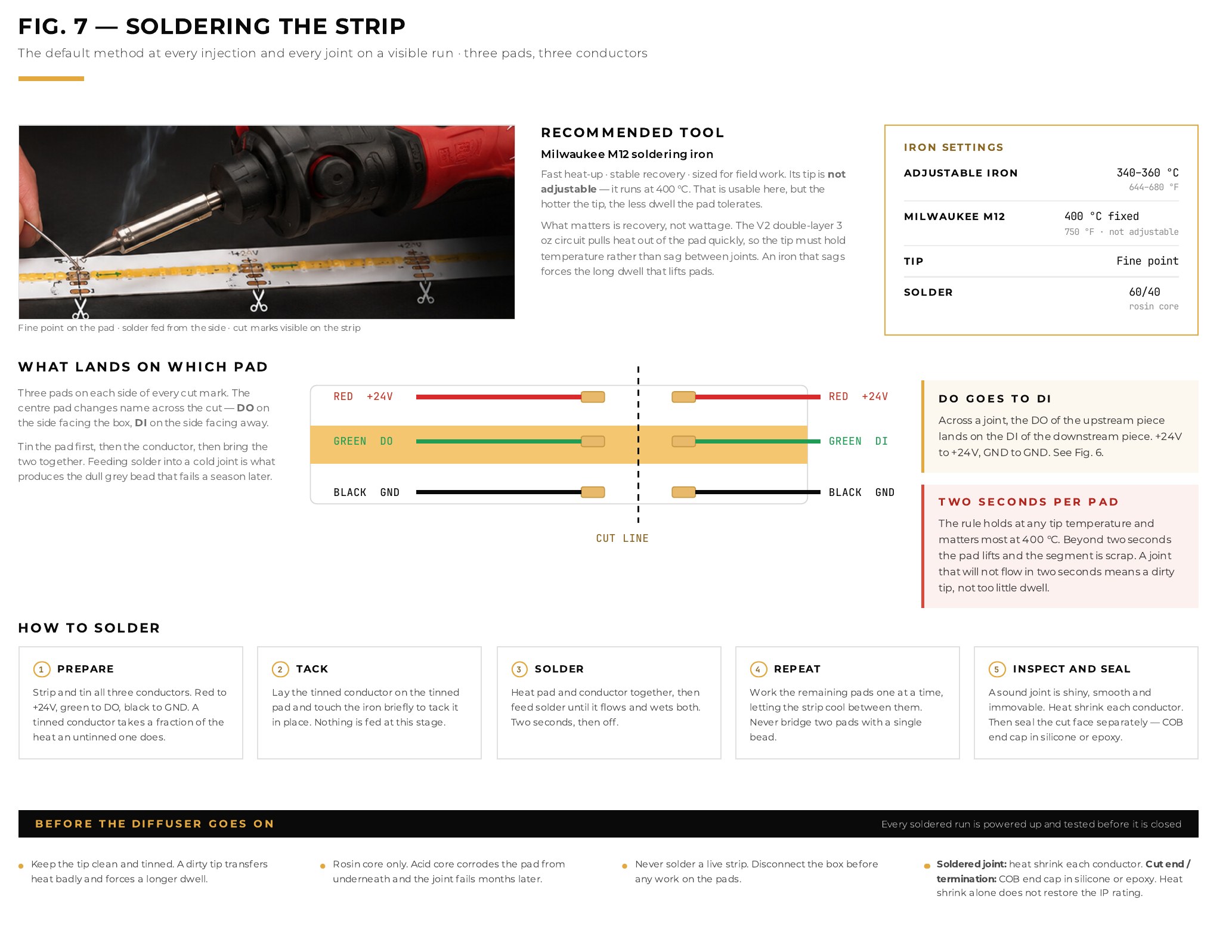
Set the iron to 340–360 °C (Milwaukee M12: fixed at 400 °C), use a fine tip, and apply heat for no more than 2 seconds per area. Red → +24V · green → DO/DI · black → GND. Clamp connectors leave a dark spot: use them only in hidden areas.

Each cut end: COB tip + silicone

Even at the end of the line, even on the inside. Whether it's silicone or epoxy, let it cure for 24 hours before closing the profile. A bare end means water will get in, and the seal will turn green within a year.

IP67 Quick Connectors

Strip-to-strip connector for feeding a cut end from a cable; strip-to-strip connector for joining two ends without soldering (COB 840 WP RGBW). Videos 02 and 03 above.

Before closing

Power the line: Any strip that remains blue is powered but is not receiving data (direction of the arrows, DO/DI, green wire). Measure 22.5 V at the end of each segment. Then check the diffusers and rail end caps.

Excerpts from the manual · Appendix A (English)
Fig. 6 of the manual: where to cut the COB strip, the three sections (+24V, DO/DI, GND), the 4-inch gap, and the four cutting steps
Fig. 6 — Cut the strip
Fig. 2 in the manual: close-up of a joint, 14/4 cable with a red-black pair on the upstream segment and a white-green pair on the downstream segment; data passing through
Fig. 2 — The gasket and the 14/4
Fig. 7 in the manual: Soldering the strip, recommended soldering iron, temperature settings, which wire color for which range, five steps
Fig. 7 — Solder the strip

05Controller Setup, in Order

Turn it on and look at the line

An unconfigured strip often lights up blue: this is normal; it is waiting for data. A strip that is off = no power; a strip that remains blue after configuration = no data.

Connect to the controller's access point

On your phone, Wi-Fi → Network IllumiDEL AP. The controller broadcasts this network as long as it is not connected to the client's Wi-Fi.

Password — old appwled1234
Password — new appillumidel1234
Settings → LEDs: type, zone, number

Type: COB (The three options are IllumiDEL Pixel RGBW · COB · Switch). Then the data area (D1 through D8) and the number of LEDs : LEDs per meter (as indicated on the roll label) × meters installed. Secure with the green hook.

Choose a color other than blue

Before saving the settings, choose a bold color: you'll immediately see what responds and what remains blue.

Wi-Fi → SCAN → client network

Select the client's Wi-Fi network (2.4 GHz), enter the password, and save; the controller will restart.

Check the IP address

Go back to Wi-Fi and confirm that the controller displays an IP address. No address = not connected: try again, check the password and the 2.4 GHz band.

Test each area, measure

100% white, zone by zone. At the far end of each segment: 22.5 V minimum. A blue zone = data (arrows, DO/DI, green wire). A blank zone = power (fuse, WAGO, output).

Put the customer back in the driver's seat

The customer downloads IllumiDEL V1 (App Store · Google Play), connects to the same Wi-Fi network, and the system appears. View a scene or a schedule. 3-year warranty; support: support@illumidel.com · 1 514 900-4018.

Procedure for the Cloud Application (V2): Coming soon.

Hands-On Training

Some skills are best learned in person.

Welding a panel in two seconds—that speaks for itself. Our hands-on training sessions allow system integrators to work with IllumiDEL systems, practice installation methods, and ask our team questions directly.