• 500+ integrators
  • 5,000+ projects completed
  • 12-year warranty on pixels
  • Designed and integrated in Canada
  • Canada · United States · Europe
  • cULus · CSA · CE · RoHS
  • Cloud or local app
  • 20 years of experience in home automation

Training Center · Pixel System

The Pixel.
Install.
Master.

Everything you need to install a Pixel system, from the first rail to handing over the keys: manual, videos, wiring cheat sheet, and controller setup guide.

First time installing?

Start here.

The three key steps for a successful Pixel setup. See the checklist below for details.

01

Think before you cut

Ten rails, 90 pixels, 60 feet per merged output. The enclosure must be 30 feet or less from the first pixel. Draw the layout on paper: rails, TAPs, outputs, zones.

02

Place it the right way up

The pixel arrows point away from the housing. Overlap the rails by ½ in. to maintain an 8-in. center-to-center spacing. White line = 24 V+.

03

Configure and then test each zone

Client's Wi-Fi, LED type, number of pixels per zone. Turn on each zone one by one before applying the end caps and silicone.

Training videos

Review. Complete. Review again if necessary.

The Pixel system capsules, followed by controller setup in the app. For COB, Strip, Neon, and the Cloud app: see the other training courses at the bottom of the page.

Pixel System 3/ 3 Capsules in a Row

Configuration — ApplicationV13 / 3 capsules in a row

Quick Reference · Pixel System

From the case to the pixels.
What you need to know by heart.

Wiring instructions and setup—all on one page. The videos above show each step; this is the version you can quickly review in five seconds on the job site.

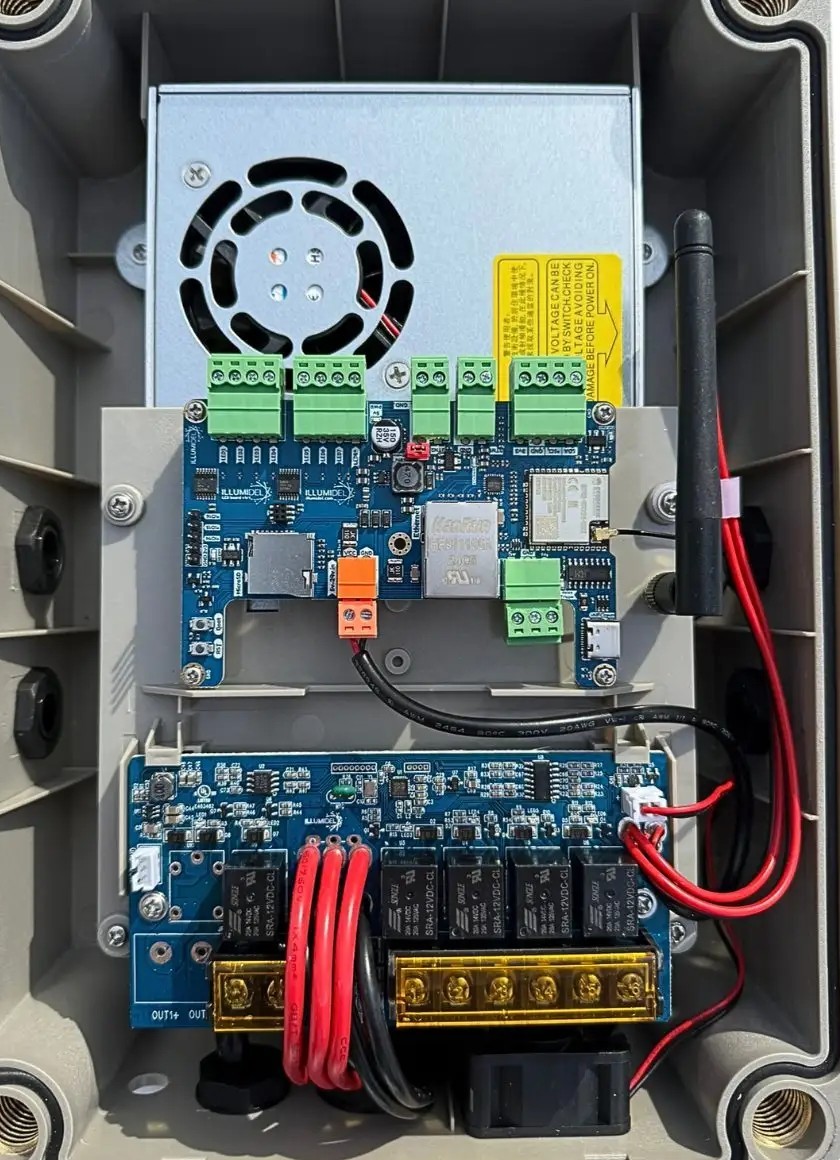
01Theenclosure: 8 data outputs on top, 4 combined outputs on the bottom

Inside the IllumiDEL The Box controller: power supply at the top, control board with 8 data terminals, output board with 4 combined outputs at the bottom 1 2 3 4 5 6
1
24 V Power Supply

450 W (3 channels) or 600 W (5 channels). Input: 100–240 V AC.

2
8 data outputs — green terminal blocks, at the top of the board

One output = one data line (GPIO 0, 1, 2, 3, 4, 5, 12, 13). The green wire runs from here to the first pixel. Independent of the power outputs.

3
Control Chart

Wi-Fi, scenes, schedules. The reset button and the microSD card are here.

4
Wi-Fi Antenna

2.4 GHz. Do not trap it under the cover.

5
4 merged 24-V outputs — gold-plated terminal block, at the bottom

5 A fuse, limited to 100 W by electronic detection. Each output powers up to 90 pixels (10 rails). The red (+) and black (−) wires run from here to the first pixel or to a TAP.

6
OUT+ / OUT− Markers

Screen-printed on the board. A data path often spans multiple merged outputs: the two accounts are independent.

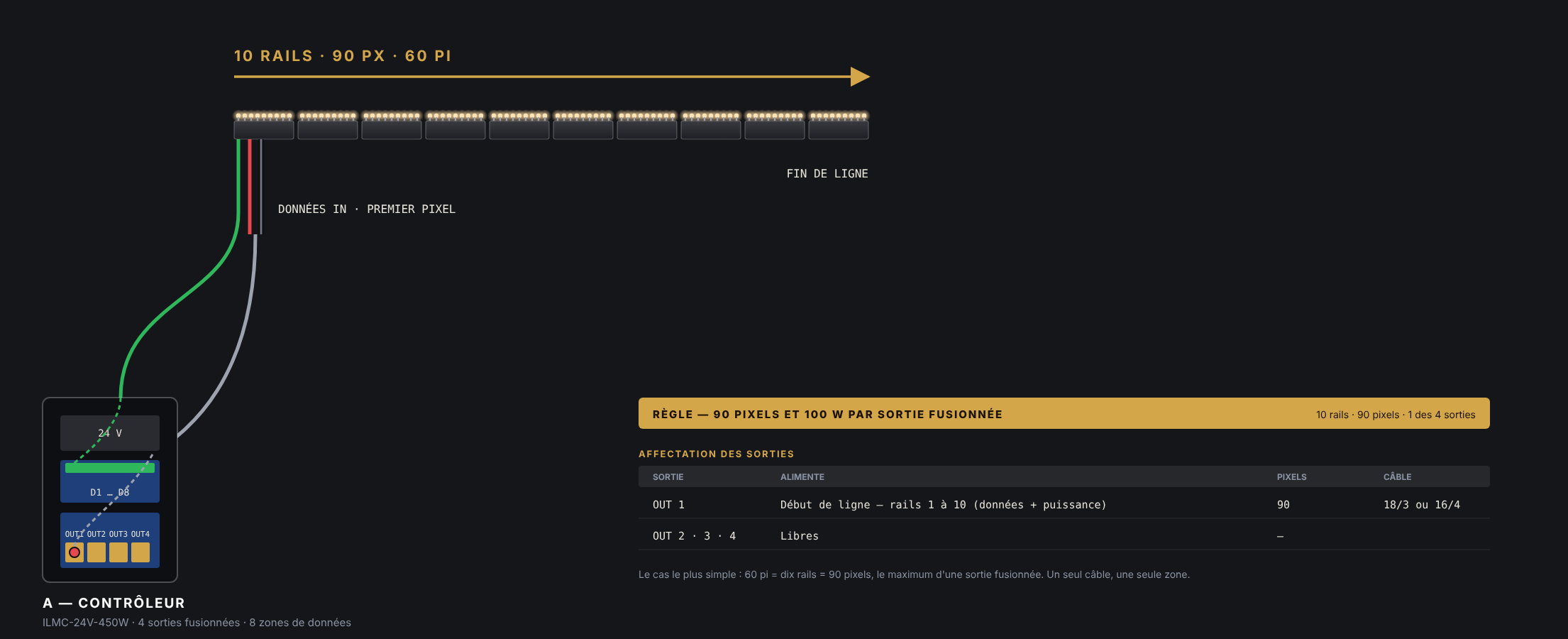
Figure 1: One controller, one data zone, ten rails, 90 pixels, 60 feet, no TAP
Fig. 1 — one controller, one zone, 60 ft. Red: +24 V Gray/black: −24 V Green: data, from the enclosure to the first pixel, in the direction of the arrows 10 rails · 9 pixels per rail · 1 combined output
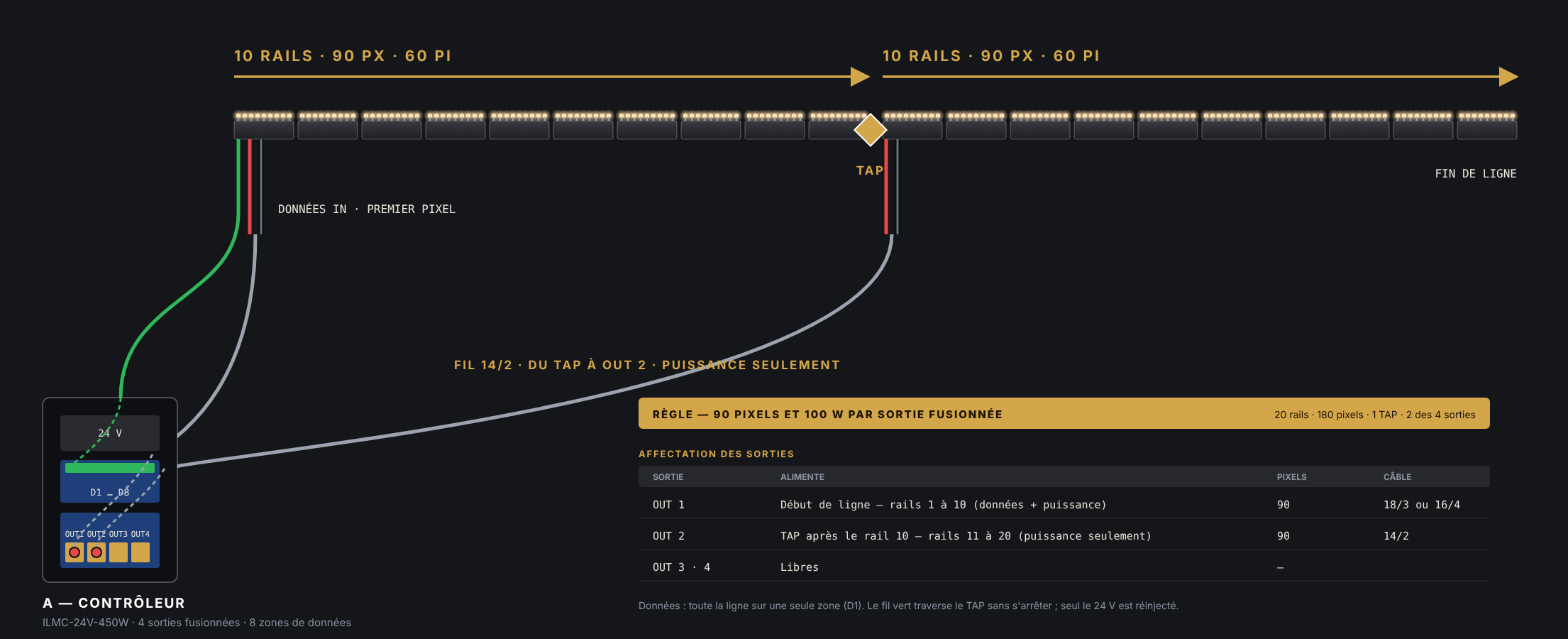
Figure 2: Twenty rails, one TAP after the tenth rail, 14/2 wire from the TAP to the second fused output of the enclosure
Fig. 2 — 20 rails, one TAP, two combined outputs. Rails 1 through 10 on OUT 1 (data + power) TAP after rail 10 Rails 11 through 20 on OUT 2 via a 14/2 wire — power only Data remains on zone D1 from start to finish

02Thepath: housing → rail → pixels, and the wire code

THE BOX 450 W · 3 channels / 600 W · 5 channels 8 OUTPUTS · top D1 D2 D3 D4 D5 D6 D7 D8 GPIO 0 1 2 3 4 5 12 13 4 MERGED 24-V OUTPUTS · Low OUT 1 OUT 2 OUT 3 OUT 4 5 A · 100 W · 90 px / output Data and power: two separate accounts enclosure within ≤ 30 ft of the first pixel DATA D1 → green wire MERGED OUTPUT 5 A · max 90 pixels 24 V+rouge · depuis OUT DONNÉESvert · depuis D1–D8 24 V−noir on the pixel and TAP wires: white line = 24 V+ RAIL 2200XL data direction → 8 in. center-to-center ½-inch overlap next track
Red = 24 V+ (cable from the enclosure) Green = Data Black = 24 V− Black with white stripe = 24 V+ (pixel and TAP wires) Arrows = Direction of current and data flow
24 V + — white wireOn the pixel, T, and TAP wires, the black wire with the white stripe is the positive. Everywhere else, black = negative. Identify the stripe before tightening.
Data — middle wireGreen from the housing. Enters only at the first pixel and passes through each TAP without interruption. Never injected along the line.
24 V − — last wireGround. With two enclosures, connect the V− wires together (14 AWG): the data line requires a common reference.

03KeyFigures to Keep in Mind

90pixelsMaximum per merged output

Ten rails spaced 6 feet 8 inches apart. On the11th rail, install a TAP and connect to another output. 100 W max: the sensor shuts off the output before the 5 A fuse blows.

8in.Center to Center

The distance between two pixels—and between two tracks as well. That distance determines the overlap.

½in.Rail Overlap

The rails overlap by about ½ inch so that the last pixel of one rail and the first pixel of the next remain 8 inches apart.

⅝inStrip the wire before connecting it to a Wago terminal

Always leave ⅝ in. of bare copper before inserting into a Wago connector, with the tab fully folded down, then apply heat-shrink tubing or electrical tape. Too short: poor contact. Too long: exposed copper.

T· tapOn a T or a TAP

The black wire with a white stripe is the 24 V+ line. The TAP only carries power—data passes through without being interrupted. Label the wire on the box side.

→arrowFollow the arrow on each pixel

The arrows point away from the housing. The first pixel in the row is closest to the housing. Check the first rail before installing the others.

Place the control box within 30 feet of the first pixel. If it’s farther away, the voltage drops over the round-trip path: move the control box closer or add a zone. Before finishing up: turn on each zone and verify that it responds fully before attaching the connectors, applying the silicone, and putting away the ladder. An inverted pixel or a Wago terminal that’s not properly secured can be found in two minutes at this stage, but it might take two hours later on.

04Controller Setup, in Order

Connect to the controller's access point

On your phone, Wi-Fi → Network IllumiDEL AP. The controller broadcasts this network as long as it is not connected to the client's Wi-Fi.

Password — old appwled1234
Password — new appillumidel1234
Open the app

The controller appears. Access its settings.

Wi-Fi Settings → Connect to the client's network

Scan, select the client's Wi-Fi network (2.4 GHz), and enter the password. Save; the controller will restart.

Check the IP address

Go back to Wi-Fi and confirm that the controller displays an IP address. No address = not connected: repeat step 3, check the password and the 2.4 GHz band.

Settings → LEDs: Type and Number

Type: IllumiDEL Pixel RGBW · SMD · Regular. Then enter the length (number of pixels) of each zone, according to the tally taken at the time of installation.

GPIO — only if a zone does not respond

The outputs are pre-assigned. If they need to be checked:

8-Zone Controller

0123451213

2-Zone Indoor Controller

1602
Test each area

Turn on each zone one by one, starting with 100% white, then a color. The number of lit pixels must match the entered count. One missing pixel at the end = incorrect count; a dead zone = GPIO or data issue.

Put the customer back in the driver's seat

The customer downloads IllumiDEL V1 (App Store · Google Play), connects to the same Wi-Fi network, and the system appears. Set up a scene or a schedule, and you're done.

Procedure for the Cloud Application (V2): Coming soon.

Hands-On Training

Some skills are best learned in person.

Our hands-on training sessions allow system integrators to work with IllumiDEL systems, practice installation methods, and ask our team questions directly.